

Icom 7300 Mic Pinout: Stop Wasting Money on the Wrong Cables (This Guide Will Save You) - An Introduction and Overview
Welcome, fellow ham radio enthusiasts and aspiring operators! If you’re the proud owner of an Icom IC-7300, you’ve undoubtedly joined the ranks of a truly remarkable radio. This SDR (Software Defined Radio) powerhouse offers an incredible blend of performance, features, and affordability, making it a favorite among both seasoned operators and newcomers to the hobby. But let’s be honest, the world of ham radio can sometimes feel like navigating a labyrinth, especially when it comes to accessories and connections. And one area that often trips up even experienced hams? Microphone connections, and specifically, getting the right microphone pinout for your Icom 7300.
This guide is your lifeline in that labyrinth. We’re here to demystify the often-confusing world of microphone pinouts, particularly for the Icom 7300. Forget the frustration of purchasing incompatible cables, struggling with poor audio quality, or even risking damage to your radio! This guide will empower you to understand the intricacies of the Icom 7300 mic connector, allowing you to confidently build, modify, or purchase the perfect microphone setup for your needs.
Why is the Icom 7300 Mic Pinout So Important?
Think of your microphone as the voice of your radio. It’s the bridge between your thoughts and the airwaves. A properly configured microphone delivers clear, crisp audio, allowing your fellow hams to understand you effortlessly. A poorly configured one, however, can result in garbled audio, background noise, and a frustrating experience for everyone involved.
The microphone pinout defines the specific connections within the microphone connector. It dictates which wires carry your audio signal, transmit keying (PTT - Push-to-Talk), ground, and other essential functions. Using the wrong pinout is like trying to speak a foreign language to your radio. It simply won’t understand you.
Here’s why understanding the Icom 7300 mic pinout is crucial:
- Audio Quality: The correct pinout ensures the proper connection of your microphone’s audio signal, resulting in clear and intelligible voice transmission.
- Functionality: It enables essential features like PTT operation, allowing you to transmit your signal.
- Preventing Damage: Incorrect wiring can potentially damage your radio or microphone, leading to costly repairs.
- Cost Savings: This guide will save you money by preventing you from buying incompatible cables or adapters that won’t work with your Icom 7300.
- Customization: Knowing the pinout allows you to personalize your setup, connecting different microphones, audio interfaces, and even building your own custom microphone cables.
- Troubleshooting: If you experience audio issues, understanding the pinout allows you to diagnose the problem more effectively.
Background Context: The Evolution of Microphone Connections
Over the years, radio manufacturers have employed various microphone connector standards. This has led to a bewildering array of connectors and pinout configurations. While some older radios used specific, proprietary connectors, modern radios, including the Icom 7300, often utilize a standardized 8-pin or RJ45 (modular Ethernet) connector.
The Icom 7300 uses an 8-pin microphone connector, which is a common and relatively versatile format. However, even within this standard, the specific pin assignments can vary between different radio models and manufacturers. This is where understanding the specific pinout for the Icom 7300 becomes paramount.
What to Expect in This Guide:
This guide will provide you with:
- A clear and concise diagram of the Icom 7300 microphone pinout.
- Detailed explanations of each pin’s function.
- Practical tips and advice on building or modifying your own microphone cables.
- Guidance on selecting compatible microphones and accessories.
- Troubleshooting tips for common audio issues.
- Links to helpful resources and further reading.
By the end of this guide, you’ll be equipped with the knowledge and confidence to connect your microphone to your Icom 7300 with ease, ensuring a smooth and enjoyable ham radio experience. So, let’s dive in and unlock the secrets of the Icom 7300 mic pinout!
Icom 7300 Mic Pinout: Stop Wasting Money on the Wrong Cables (This Guide Will Save You!) - A Deep Dive
The Icom IC-7300 is a popular and capable Software Defined Radio (SDR) transceiver. One of the most common frustrations for new and experienced hams alike is dealing with the microphone connector and its associated pinout. This guide will provide a comprehensive understanding of the IC-7300 microphone pinout, helping you avoid costly mistakes and ensuring you get the most out of your radio. We’ll cover the why, the how, and the what-to-watch-out-fors, so you can confidently build or purchase the correct microphone cable for your needs.
Why is Understanding the Mic Pinout Crucial?
Before diving into the pinout itself, let’s establish why this is so important:
- Functionality: The microphone connector is the lifeline for your audio transmission. Incorrect wiring will lead to:
- No audio transmission: You won’t be heard.
- Poor audio quality: Distorted, low-volume, or noisy audio.
- PTT (Push-To-Talk) malfunction: You might not be able to key the radio.
- Other control issues: Depending on the accessories you connect, you might lose control of things like up/down frequency control.
- Cost Savings: Pre-made microphone cables can be expensive, especially if you buy the wrong one and it doesn’t work. Understanding the pinout allows you to:
- Build your own cables: This is significantly cheaper than buying pre-made ones, especially if you already have the necessary components.
- Identify and fix problems: If your cable isn’t working, you can troubleshoot it easily by understanding the pinout.
- Adapt existing microphones: If you have a microphone with a different connector, you can adapt it to the IC-7300 using the pinout information.
- Avoiding Damage: Incorrect wiring can potentially damage your radio. While the IC-7300 is generally robust, connecting incorrect voltages or short-circuiting pins can cause problems.
- Flexibility and Customization: Knowing the pinout empowers you to customize your setup. You can add features like:
- Foot switches for PTT: For hands-free operation.
- External speakers: For improved audio monitoring.
- Microphone gain control: For fine-tuning audio levels.
The IC-7300 Microphone Connector: The 8-Pin Modular Connector
The IC-7300 uses a standard 8-pin modular connector, often referred to as an RJ-45 connector (though the pin assignments are not the same as for Ethernet). This connector is commonly used in networking, but the pin assignments are specific to the radio’s microphone interface. You’ll need to be familiar with the numbering of the pins, which is crucial for accurate wiring.
The Pinout Diagram: Unveiling the Secrets
Here’s the official pinout diagram for the IC-7300 microphone connector. This is the most critical piece of information you need. It’s essential to refer to this diagram when wiring your cable.
| Pin | Function | Description |
|---|---|---|
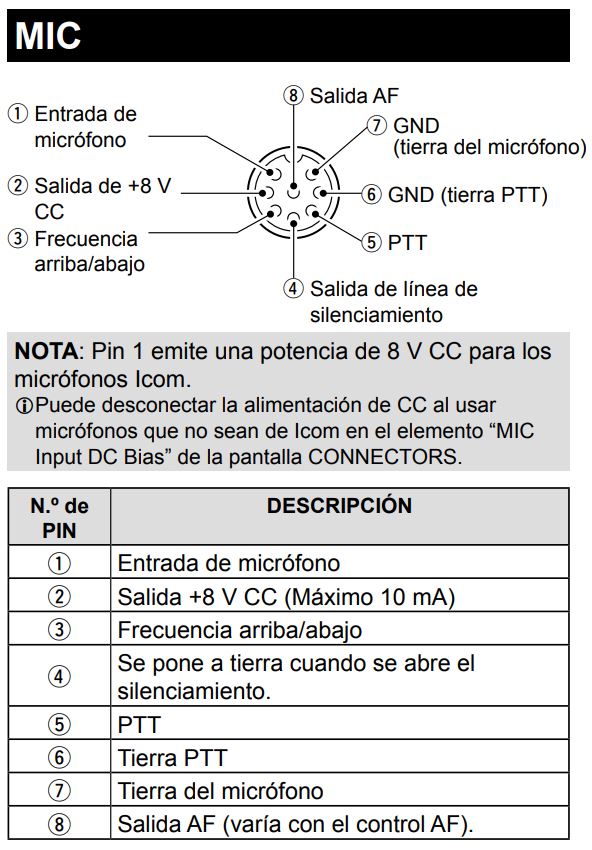
| 1 | MIC | Microphone Audio Input (Signal) |
| 2 | GND | Microphone Audio Ground (Signal Ground) |
| 3 | PTT | Push-To-Talk (Keying) - When grounded, the radio transmits. |
| 4 | UP/DOWN | Frequency Up/Down Control (Optional - requires compatible microphone) |
| 5 | GND | Ground (Common Ground - for PTT, UP/DOWN, and sometimes for other functions) |
| 6 | +8V (DC) | Microphone Bias Voltage (Provides power for electret microphones - typically 8V, but can vary slightly) |
| 7 | NC (Not Connected) | Not Connected - Do Not Use. |
| 8 | AF OUT | Audio Output (Speaker Audio - can be used to feed an external speaker or other audio equipment) |
Explanation of Each Pin and its Purpose:
- Pin 1: MIC (Microphone Audio Input): This is where the audio signal from your microphone enters the radio. Connect the positive (signal) wire of your microphone to this pin.
- Pin 2: GND (Microphone Audio Ground): This is the ground connection for the microphone audio. Connect the negative (ground) wire of your microphone to this pin. Crucially, this is the audio ground, separate from the common ground.
- Pin 3: PTT (Push-To-Talk): This pin is used to key the radio for transmission. When this pin is connected to ground (Pin 5), the radio transmits. This is typically activated by pressing the PTT button on your microphone.
- Pin 4: UP/DOWN (Frequency Control): This pin allows you to control the radio’s frequency using up/down buttons on a compatible microphone. This is an optional feature. You’ll need a microphone that supports this functionality. The exact wiring for up/down control can vary depending on the microphone design, often involving resistors and switches.
- Pin 5: GND (Common Ground): This is a common ground connection for the PTT circuit and is often used for other functions. This is the ground reference for the PTT circuit. Connect the ground wire of your PTT switch to this pin.
- Pin 6: +8V (DC) (Microphone Bias Voltage): This pin provides power (typically +8V DC) to power electret microphones. Important: If your microphone doesn’t require bias voltage, you don’t need to connect to this pin. Providing the wrong voltage, or shorting this pin to ground, can damage your radio or microphone. Most modern microphones use electret elements and require this voltage.
- Pin 7: NC (Not Connected): This pin is not connected internally in the radio. Do not connect anything to this pin.
- Pin 8: AF OUT (Audio Output): This pin provides the audio output from the radio. You can connect this to an external speaker, a sound card for digital modes, or other audio equipment.
Steps to Build Your Own Microphone Cable (or Troubleshoot Existing Ones):
- Gather Your Materials:
- An 8-pin modular connector (RJ-45 type). Purchase a connector with the right configuration, making sure it’s designed to handle the wires you’ll be using. You can find these at electronics stores or online.
- Appropriate wire: Use shielded, stranded wire for the microphone audio (Pin 1 and 2) to minimize noise. Use separate wires for PTT (Pin 3) and optional features. The gauge of wire doesn’t need to be very thick, but it should be manageable for the connector.
- A microphone: Determine the microphone type (dynamic or electret). If it’s electret, you’ll need to connect to Pin 6 (+8V).
- A soldering iron and solder.
- Wire strippers/cutters.
- A crimping tool (for the RJ-45 connector, if required - some connectors are solder-type).
- A multimeter (for testing continuity and voltages).
- Heat shrink tubing (optional, but recommended for insulation).
- Prepare the Wires:
- Cut the wires to the desired length.
- Strip the ends of the wires to expose the conductors.
- If using shielded wire, prepare the shield (either by stripping it back and twisting it, or by connecting it to ground).
- Connect the Wires to the Microphone:
- Refer to the microphone’s documentation to identify the audio signal (positive), audio ground, and PTT connections. These may be labeled as “MIC,” “GND,” “PTT,” etc., or have color-coding.
- Connect the microphone audio (positive) wire to the microphone’s audio input.
- Connect the microphone audio ground wire to the microphone’s ground.
- Connect the PTT switch to the microphone’s PTT connection and ground.
- If your microphone requires bias voltage (electret microphone), connect the appropriate wire from your microphone to the +8V (Pin 6) on the RJ-45 connector. Ensure you have the correct polarity.
- Wire the RJ-45 Connector:
- Option 1: Soldering: If your connector allows soldering:
- Carefully solder the wires to the correct pins on the RJ-45 connector, following the pinout diagram above.
- Use heat shrink tubing to insulate the solder joints.
- Option 2: Crimping: If your connector uses a crimping method:
- Insert the wires into the RJ-45 connector in the correct order, according to the pinout diagram.
- Use the crimping tool to secure the wires in the connector.
- Option 1: Soldering: If your connector allows soldering:
- Test the Cable:
- Use a multimeter to test for continuity between the corresponding wires and the pins on the RJ-45 connector. This verifies that your connections are solid.
- If you’re using an electret microphone, measure the voltage on Pin 6 (+8V) with a multimeter to confirm that you’re providing the correct bias voltage.
- Connect the cable to the IC-7300 and test the microphone by transmitting and listening to your audio.
- Test the PTT function.
- If you have a microphone with UP/DOWN control, test those buttons.
Examples and Considerations:
- Dynamic Microphone: Dynamic microphones do not require bias voltage. Connect the audio signal (positive) to Pin 1 (MIC) and the audio ground to Pin 2 (GND). Connect the PTT switch to Pin 3 (PTT) and Pin 5 (GND).
- Electret Microphone: Electret microphones do require bias voltage. Connect the audio signal to Pin 1 (MIC), the audio ground to Pin 2 (GND), the PTT switch to Pin 3 (PTT) and Pin 5 (GND). Also, connect the microphone’s positive voltage wire to Pin 6 (+8V).
- Adapting a Microphone with a Different Connector: If you have a microphone with a different connector (e.g., a 1/4" phone plug or a different 8-pin connector), you’ll need to use an adapter cable or rewire the existing microphone cable. The key is to identify the function of each wire in your existing microphone cable and connect them to the corresponding pins on the IC-7300’s RJ-45 connector.
- Using an External Speaker: Connect the audio output (Pin 8) to the input of your external speaker or amplifier. You may also need to connect a ground wire from the speaker to a ground on the radio (Pin 5 is often used).
- Troubleshooting:
- No Audio: Check the microphone wiring (Pin 1, Pin 2, and audio connection in the microphone). Verify the microphone is powered (if electret). Check the radio’s microphone gain settings.
- Poor Audio Quality: Check the wiring for noise. Make sure the audio ground is properly connected. Check the radio’s audio settings (equalizer, compression, etc.). Use shielded cable.
- PTT Not Working: Verify the PTT wiring (Pin 3 to Pin 5). Check the PTT switch in the microphone. Check the radio’s PTT settings.
- UP/DOWN Not Working: Verify the UP/DOWN wiring (Pin 4). Make sure the microphone is compatible with the IC-7300’s UP/DOWN control. Check the radio’s settings.
Key Takeaways and Summary:
- Pinout is King: Memorize, or at least have readily available, the IC-7300 microphone pinout diagram.
- Understand Microphone Types: Know the difference between dynamic and electret microphones and their power requirements.
- Shielded Cable is Your Friend: Use shielded cable for the microphone audio to minimize noise.
- Double-Check Your Connections: Before plugging the cable into the radio, carefully verify all connections with a multimeter.
- Test, Test, Test: Thoroughly test your cable after building it to ensure it works correctly.
- Don’t Be Afraid to Build Your Own: Building your own cable saves money and gives you greater flexibility.
- Troubleshooting is Easier with Knowledge: Understanding the pinout makes troubleshooting any problems significantly easier.
By following this guide, you’ll be well-equipped to create or adapt microphone cables for your Icom IC-7300, saving you money, improving your audio quality, and enhancing your overall operating experience. Happy transmitting!
Icom IC-7300 Microphone Pinout FAQ: Stop Wasting Money on the Wrong Cables (This Guide Will Save You)
This FAQ is designed to answer your most pressing questions about the microphone pinout for the Icom IC-7300 transceiver. We’ll cover everything from the basics to advanced configurations, helping you avoid costly mistakes and get your radio on the air quickly and correctly.
General Questions
Q1: What is a microphone pinout, and why is it important for my IC-7300?
A1: A microphone pinout is the diagram that shows which pin on your microphone connector (usually an 8-pin or RJ45) corresponds to specific audio and control signals. For the IC-7300, knowing the pinout is critical because it defines how your microphone transmits audio, PTT (Push-to-Talk), and any other control functions. Using the wrong pinout can result in no audio, garbled audio, constant transmit, or even damage to your radio. This guide will help you select or build the correct cable, saving you money and frustration.
Q2: Where can I find the correct microphone pinout for my IC-7300?
A2: The official Icom IC-7300 manual provides the correct pinout information. You can also find it below in the “Detailed Pinout Information” section of this FAQ. This is the definitive source. Always double-check your source and compare it to the manual.
Q3: What type of microphone connector does the IC-7300 use?
A3: The IC-7300 uses an 8-pin round microphone connector. It’s a standard type found on many amateur radio transceivers.
Q4: Why are there so many different microphone cable options available?
A4: Different radios use different pinouts. Also, some microphones have built-in features that require specific wiring. This creates a wide variety of cable options. Buying a cable without knowing the correct pinout for your IC-7300 is a common mistake and often leads to disappointment.
Q5: Can I use a microphone designed for another radio with my IC-7300?
A5: Potentially, yes, but not without modification. You’ll need to rewire the microphone connector or build an adapter cable to match the IC-7300 pinout. Simply plugging in a microphone designed for a different radio is highly unlikely to work and could potentially damage your equipment.
Q6: Is it better to buy a pre-made cable or build my own?
A6: Both options have pros and cons:
- Pre-made cables: Convenient and readily available. However, you need to ensure the pinout is correct for the IC-7300. Read reviews and verify before buying.
- Build your own: Allows for customization and ensures the correct pinout. You can also choose high-quality components. This is a great option if you have some basic soldering and wiring skills.
Q7: What tools and materials do I need to build my own microphone cable?
A7: You’ll need:
- An 8-pin round microphone connector (male, to plug into the radio)
- A microphone connector (female, for your microphone) – This depends on your mic type (e.g., 4-pin XLR, RJ45, etc.)
- Shielded microphone cable (2-4 conductor, depending on your mic’s needs)
- Soldering iron and solder
- Wire strippers
- Multimeter (for testing connectivity)
- Heat shrink tubing (optional, for insulation)
Q8: What if my microphone has a different connector than the IC-7300?
A8: You’ll need to create an adapter cable. For example, if your microphone uses an RJ45 connector, you’ll need a cable with an 8-pin round connector on one end (for the IC-7300) and an RJ45 connector on the other. The wiring inside the adapter cable must match the IC-7300 pinout for the relevant functions.
Q9: Where can I buy the components for building a microphone cable?
A9: You can find these components at electronics supply stores (online or brick-and-mortar), amateur radio supply stores, and even some hardware stores.
Q10: Is there a risk of damaging my IC-7300 when using a microphone?
A10: Yes, there is a risk if you use a cable with the wrong pinout or if you connect the wrong wires. Incorrect wiring can lead to:
- No audio: Incorrect audio wiring.
- Constant transmit: PTT wire shorted or incorrectly wired.
- Garbled audio: Audio wiring issues, incorrect impedance matching, or interference.
- Damage to the radio: Connecting the wrong signals to the wrong pins could potentially damage the radio’s internal components. This is why it’s crucial to verify the pinout.
Detailed Pinout Information
Q11: What is the official IC-7300 microphone pinout?
A11: Here is the pinout for the 8-pin microphone connector on the IC-7300, as specified in the Icom manual:
| Pin | Function | Description |
|---|---|---|
| 1 | GND | Ground (Audio and PTT Return) |
| 2 | MIC | Microphone Audio Input (High Impedance) |
| 3 | PTT | Push-to-Talk (Active Low - connects to GND to transmit) |
| 4 | UP/DOWN | Microphone Up/Down (Optional, may not be supported by all microphones) |
| 5 | CW KEY | CW Key Input (Optional, typically not used for microphone operation, connects to the radio for keying) |
| 6 | +8V | +8V DC Output (for electret microphones or external circuitry) – Limited Current Capacity! (See Q13) |
| 7 | NC | No Connection (Not Used) |
| 8 | Shield/GND | Shield or Ground (Connects to the microphone cable shield, also a return ground for the microphone audio signal) |
Q12: How do I use this pinout to wire a microphone cable?
A12:
- Identify your microphone’s wiring: Refer to your microphone’s documentation to determine which wires correspond to audio, PTT, ground, etc.
- Connect the wires: Use the pinout above to connect the microphone wires to the 8-pin connector. For example:
- Connect the microphone’s audio wire to Pin 2 (MIC).
- Connect the microphone’s PTT wire to Pin 3 (PTT).
- Connect the microphone’s ground wire to Pin 1 (GND) and Pin 8 (Shield/GND).
- Connect the microphone’s shield wire (if any) to Pin 8 (Shield/GND).
- Test the cable: Use a multimeter to verify continuity between the pins and the corresponding wires in your microphone. Double-check your connections.
Q13: Can I power my electret microphone from the +8V pin (Pin 6)?
A13: Yes, but with caution. The +8V pin provides a limited amount of current. Do not exceed the current rating specified in the IC-7300 manual. Typically, this is a few milliamps (e.g., 10mA or less). Overloading the +8V pin can damage the radio. Use a current-limiting resistor (usually 1k to 10k ohms) in series with the +8V supply to protect the radio and the microphone. Consult your microphone’s specifications for its voltage and current requirements.
Q14: How do I test my microphone cable to ensure it’s wired correctly?
A14:
- Visual Inspection: Carefully inspect your solder joints for any shorts or cold solder joints.
- Continuity Test: Use a multimeter set to “continuity” (or resistance) to test the connections.
- Ground: Test for continuity between Pin 1 (GND) and Pin 8 (Shield/GND) on the 8-pin connector and the microphone’s ground wire.
- Audio: Test for continuity between Pin 2 (MIC) on the 8-pin connector and the microphone’s audio wire.
- PTT: Test for continuity between Pin 3 (PTT) on the 8-pin connector and the microphone’s PTT wire. When you press the PTT button on your microphone, the multimeter should show continuity.
- Audio Test: Connect the cable to your IC-7300 and transmit. Listen to your audio on another receiver or ask someone to listen for you.
- PTT Test: Ensure that pressing the PTT button on your microphone engages the transmitter.
Common Problems and Solutions
Q15: My audio is very quiet or distorted. What could be wrong?
A15: Common causes include:
- Incorrect wiring: Double-check the audio wire connection (Pin 2).
- Microphone impedance mismatch: The IC-7300 expects a high-impedance microphone. Using a low-impedance microphone without a proper impedance matching transformer will result in very quiet audio.
- Incorrect microphone gain settings: Check the microphone gain settings in your IC-7300’s menu.
- Poor solder joints or faulty cable: Inspect the cable and connections.
- Shielding issues: Make sure the microphone cable is properly shielded and grounded. Run a ground wire from the metal chassis of your microphone to Pin 8.
- Incorrect mic bias voltage: If you’re using an electret mic, the bias voltage might be set incorrectly. The IC-7300 usually provides +8V, which should be suitable, but make sure the microphone is correctly wired to Pin 6.
Q16: My radio is constantly transmitting. What should I do?
A16: This usually indicates a short circuit in the PTT circuit:
- Incorrect wiring: Double-check the PTT wire connection (Pin 3).
- Shorted PTT wire: The PTT wire may be touching ground.
- Faulty microphone switch: The PTT switch in your microphone may be faulty.
- Internal radio fault: While less likely, a fault in the radio’s PTT circuit is possible.
Q17: The UP/DOWN buttons on my microphone don’t work. How do I fix this?
A17: The IC-7300 may not support the UP/DOWN feature on all microphones. Check the microphone’s documentation to see if it’s compatible. If the microphone should work:
- Incorrect wiring: Double-check the wiring for the UP/DOWN function (Pin 4). The pinout for the UP/DOWN function is not standardized, and may not work with all microphones. Consult your microphone’s documentation to determine the wiring.
- Microphone not compatible: The microphone might not be designed to work with the IC-7300’s UP/DOWN control.
- Radio settings: Ensure the UP/DOWN function is enabled in the IC-7300’s menu settings.
Q18: I’m getting hum or noise in my audio. What could be causing this?
A18: Common causes of hum or noise:
- Ground loops: Ensure proper grounding of all your equipment. This is the most common cause. Connect the microphone cable shield (Pin 8) to the microphone’s chassis.
- Poor shielding: Use a shielded microphone cable and ensure the shield is properly connected to ground at both ends.
- Interference: Keep the microphone cable away from power cords and other sources of electromagnetic interference.
- Power supply noise: If you’re powering your microphone or other accessories from the same power supply as your radio, the power supply may be introducing noise.
- Faulty microphone: The microphone itself may be the source of the noise.
Q19: Can I use a Heil Sound microphone with my IC-7300?
A19: Yes, you can. Heil Sound microphones are designed for amateur radio use. However, you’ll likely need to purchase a specific Heil cable that is wired for the IC-7300. Do not assume a Heil cable for another radio will work. Check Heil Sound’s website or contact them directly to confirm the correct cable for your microphone model and the IC-7300. You may also need to adjust the IC-7300’s microphone gain settings for best performance.
Q20: I bought a cable that was supposed to work, but it doesn’t. What should I do?
A20:
- Verify the pinout: Carefully compare the cable’s wiring to the IC-7300 pinout (provided above).
- Check for internal wiring issues: Inspect the connectors for any loose wires or faulty connections.
- Contact the seller: If the cable was advertised as being compatible with the IC-7300, contact the seller and explain the problem. You may be able to get a replacement or a refund.
- Consider building your own cable: If you’re comfortable with soldering, building your own cable is a reliable way to ensure the correct pinout.
By following this FAQ, you should be well-equipped to understand the IC-7300 microphone pinout and to build or select a cable that works correctly. Remember to always consult the official Icom IC-7300 manual for the most accurate and up-to-date information. Happy transmitting!
Icom 7300 Mic Pinout: Stop Wasting Money on the Wrong Cables (This Guide Will Save You) - Conclusion and Summary
This guide has illuminated the often-confusing world of microphone pinouts for the Icom 7300, empowering you to ditch the expensive and potentially incorrect pre-made cables. We’ve navigated the intricacies of the 8-pin and RJ45 microphone connectors, dissected the essential connections for audio input, PTT, and ground, and provided you with the knowledge to confidently build or modify your own custom microphone cables.
Recap of Key Points:
- Understanding the Pinout: We’ve demystified the Icom 7300’s microphone pin assignments, specifically the 8-pin and RJ45 configurations, allowing you to identify the purpose of each wire.
- Essential Connections: We focused on the critical connections for audio input (microphone audio, or MIC), Push-to-Talk (PTT), and ground, ensuring clear and reliable communication.
- DIY Empowerment: This guide encourages DIY solutions, providing the information needed to build or modify your own cables, saving you money and offering greater control over your setup.
- Avoiding Common Pitfalls: We’ve highlighted the risks of relying on generic or improperly wired cables, preventing frustration and potential damage.
- Troubleshooting Tips: We’ve offered practical advice for troubleshooting audio issues and ensuring a clean signal.
Final Thoughts:
The ability to build your own microphone cables isn’t just about saving a few dollars; it’s about taking ownership of your ham radio setup. It’s about understanding the underlying technology, troubleshooting effectively, and tailoring your equipment to perfectly match your needs. By mastering the Icom 7300 mic pinout, you’ve gained a valuable skill that will serve you well throughout your amateur radio journey. No longer will you be at the mercy of pre-made cables that may or may not work. You are now equipped to control your audio experience.
Actionable Takeaways:
- Review the Pinout Diagrams: Keep the provided pinout diagrams handy for future reference when working with your Icom 7300.
- Gather Your Materials: Assemble the necessary components (connectors, wire, solder, etc.) to build your own cables.
- Start Small: Begin with a simple cable, such as a straight-through extension cable, to practice your soldering and wiring skills.
- Test Thoroughly: Always test your custom-built cables before using them on the air to ensure proper functionality and avoid any unexpected issues.
- Share Your Knowledge: Help other hams by sharing this guide and your newfound expertise!
Next Steps:
Now that you’ve mastered the Icom 7300 microphone pinout, it’s time to put your knowledge into action! Grab your soldering iron, gather your components, and build your own custom microphone cable today! You’ll be amazed at the difference a perfectly wired cable can make in your audio quality and overall operating experience. Happy transmitting, and 73!
